Wireless Sensor Systems
The wireless sensor system consists of PC software, a PC interface and 1-4 wireless sensor modules.
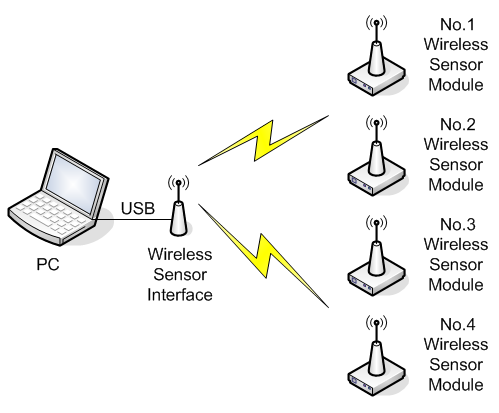
To each wireless sensor module 3 analog signals can be connected. Also each board has 2 relay outputs and an onboard LM35 temperature sensor. The inputs are measured at a 1 Hz sample rate and the data is radio transmitted to the PC software. The software will show the live data in graphs and numbers.
All measurements can be traced to files. In this mode the system works like a datalogger and can store measurement data over long periods of time (days, weeks). A total of 4 x 3 analog signals can be logged this way.
Using the onboard relays and programmable logic rules (both relays can be switched on/off automatically based on the measured values of the input channels), simple "smart" controllers can be made.
Specifications
Wireless Sensor Interface.
Powered from USB.
433 MHz frequency band.
Tx & Rx status LEDs.
FTDI USB interface chip & drivers.
USB Type A connector.
Wireless Sensor Module (Type 2)
3x 10 bits analog inputs, 5 V range.
1x temperature sensor, -25 degC to +100 degC range.
2x digital relay outputs.
433 MHz frequency band.
Selectable module ID.
7.5 V - 10 V supply voltage.
1 Hz input sample rate.
Up to 4 modules can be used together.
PC Software
Windows based. Supported versions: 2000, XP, Vista, Window 7
Royalty free FTDI drivers (http://www.ftdichip.com/Drivers/D2XX.htm)
Hardware
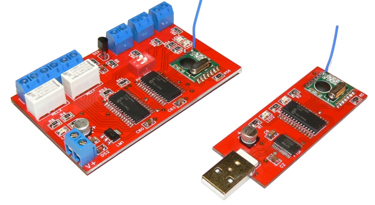 Left: Wireless Sensor Module & Right: Pc Interface
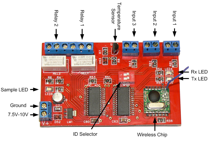 Wireless Sensor Module explanation