Software
Click here
to download the windows software.
Click here
to download an example trace file.
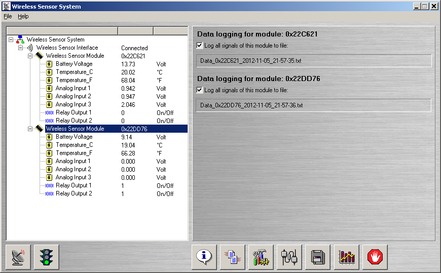
Main program window with settings dialog
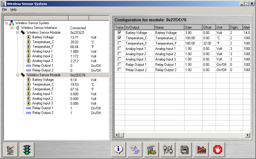
When the program is started, the main window is displayed (see picture below). On the LEFT side in this window a tree shows the wireless sensor modules which are online. On the RIGHT side various module specific information is displayed.
 | Click this icon to scan for wireless modules. The software will do a scan and list all modules which are online in the tree view in the program window. |
 | Click this icon to start / stop automatic update (1 Hz) of all the modules. |
 | Click this icon to open the information panel in which system loggging information is displayed. Usefull when detailed information is needed over the system (version numbers, serial numbers, etc). |
 | Click this icon to display the wireless statistics panel. In this panel, information about packets send / received for each module is displayed. Also bad transmissions are counted. |
 | Click this icon to display the settings panel. In the settings panel, it is possible to edit the names, gains, units and digits of each signal of each module. |
 | Click this icon to display the digital outputs panel. In this panel, the digital outputs of the sensor modules can be controlled. There are 3 options: Off, On or Rule based. |
 | Click this icon to display the datalogging panel. In this panel, logging of all meausured signal to file can be switch on/off. Switch the logging on to use the modules as dataloggers. |
 | Click this icon to display the Trace Window. In this window the time traces are displayed for the signals which are traced (see Settings Panel to select tracing for signals). |
 | Click this icon to display the Alarm Window. In this window the alarms are shown for sensors have tripped the high / low alarm levels. |
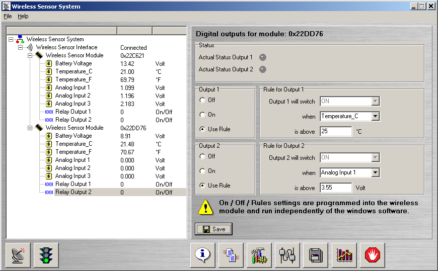
Digital outputs & rules to switch outputs
The 2 relay outputs of each module can be switch on / off either
manually of
based on logic rules. The picture below shows the panel in which these rules can be changed and (de)activated. These rules are
programmed into the modules and updated at a 1 Hz update rate. If the software is stopped, the rules will
continue to run in the sensor modules.
Examples:
In figure below relay #1 will switch on when the
Temperature_C comes above 25 DegC.
In figure below relay #2 will switch on when the
Analog input #1 comes above 3.55 Volt.
The rules are stored in the EEPROM of the sensor module and reloaded after power-up of the module.
Data logging window
Of each module all the signals can be logged to file(s). This makes it possible to monitor signals over longer times (days, weeks) by writing them to file(s). A sample logfile can be downloaded on top of this webpage.
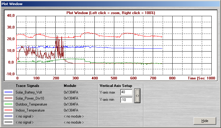
Trace window
In the settings panel signals can be selected for tracing. In the
trace window each selected signal is shown with an 1 Hz update rate. Upto 6 signals can be traced together.